Create Supertin
This option is used to create a super triangulation, i.e. a Supertin. Using other triangulations and combine them together based on a list order of the Tins selected.
Continue down the page to see the Create Supertin Panel options.
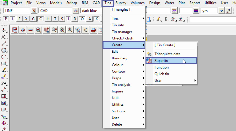
To view the Create Supertin Panel, Use: Tins => Create => Supertin
Definition
A Supertin is designed to combine existing triangulations to form the equivalent of a merged triangulation without having to completely re-build a merged model and triangulating it. This means that there are less steps in creating a Supertin so a lot less time is required and there is less opportunity for errors.
If any of the triangulations that make up the Supertin are modified, then the Supertin is also instantly modified and updated.
Firstly type in the Super Tin name, this must be unique for the project. Then hit the key and the Model name for the Super Tin will be automatically filled out. This is very good house-keeping to ensure that the tin and model names have a naming convention.
The Tin Colour set here is the colour of the Supertin when sectioning through it.
When displayed on the plan view each tin making up the Supertin is drawn in its own colour.
The Tin Style is the linestyle used for drawing sections through the tin on the section view.
The Exact Calculations tick box if ticked when a Supertin is created or a tin in the Supertin is modified, extra calculations are done for the Supertin so that it can be used for Exact Volumes and in Visualisations. If not ticked, no extra calculations are done and the Supertin can only be used for sections, i.e. end area volumes and site lines.
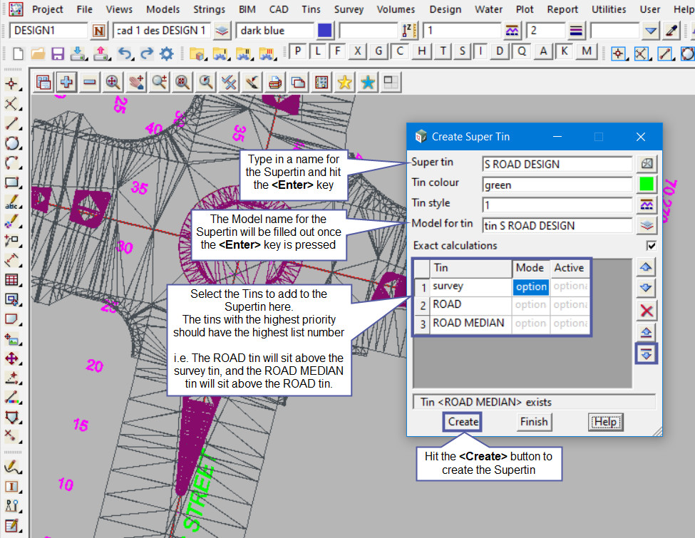
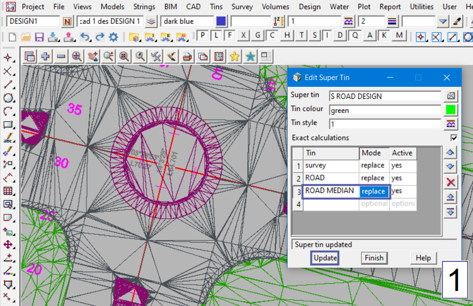
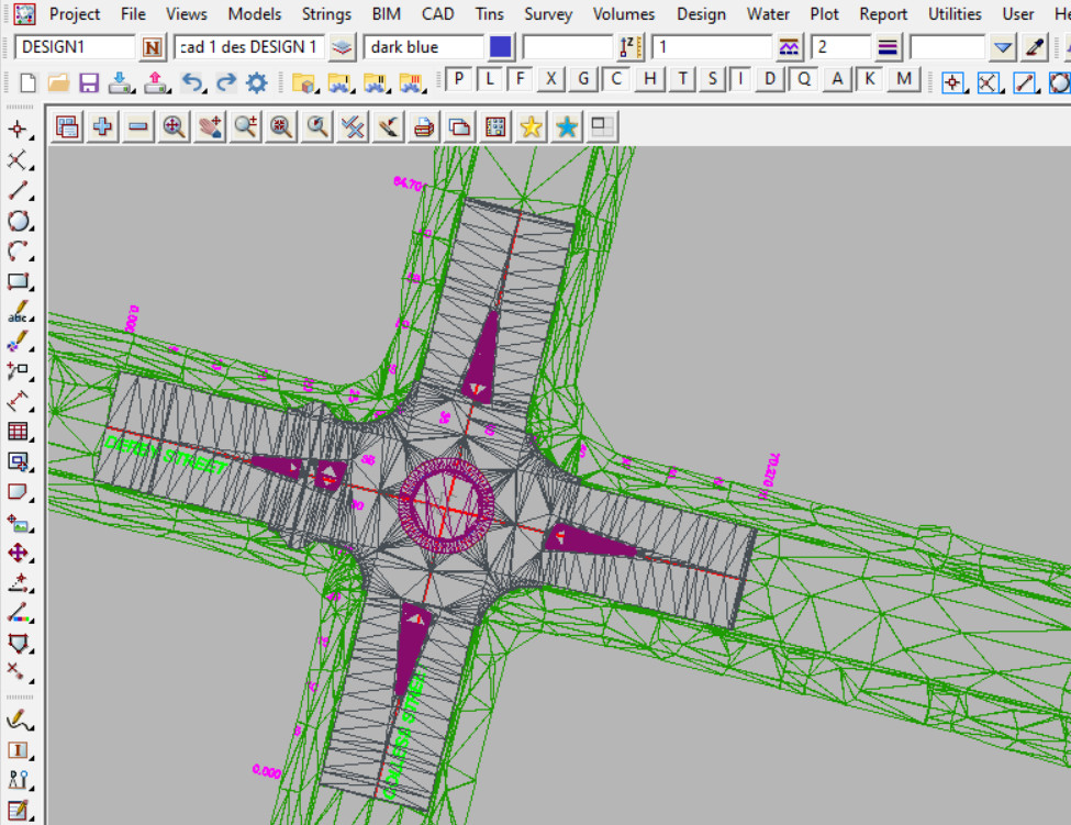
Here the Supertin has been created and as shown the three tins can be clearly seen, but the tins with a higher list number are shown above the other tins.
The Tins are shown:
- The Survey tin (green) is only shown where the other tins do not occur, as it has the lowest priority,
- The ROAD tin (dark grey) is shown everywhere but for where the ROAD MEDIAN tin (purple) is, as it has the highest priority.
Tin Grid
Where the list of Tins are selected, there are also options available for each tin.
The Mode option, has two choices:
- Replace – wherever this tin exists, use it instead of any tins of a lower number in the Tin column. This is the default option.
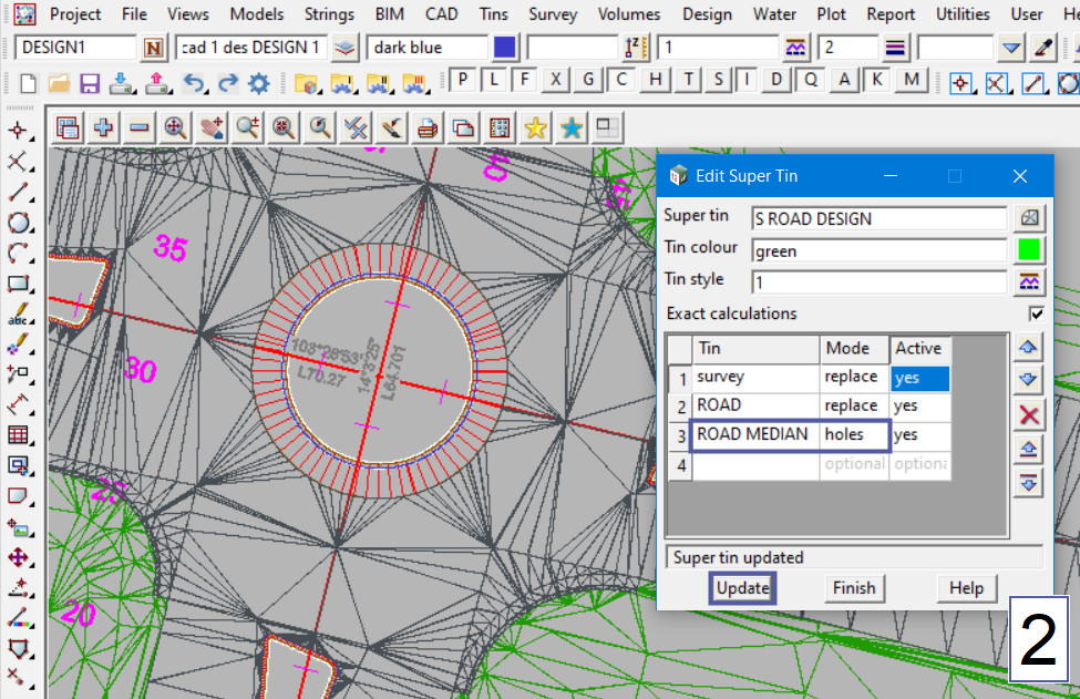
- Holes – wherever this tin exists, all parts of the tins of a lower number in the Tin column, are removed, so wherever this tin exists it will create holes in all the tins of a lower number in the Tin column.
i.e. An example would be for a tin of many gully pits, holes would be punched in all the tins at those locations. Basically nulling the parts of the triangles from the lower numbered tins.
Note: Remember to hit the button to update the Supertin.
The Active Mode, has two options:
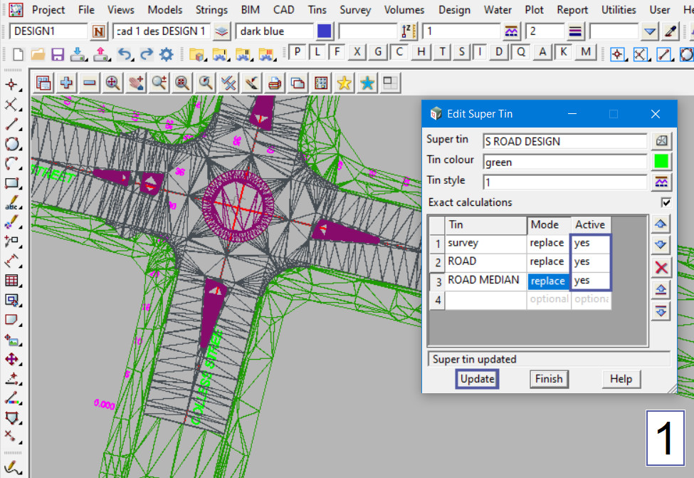
- Yes – if Yes then the tin is included in the Supertin.
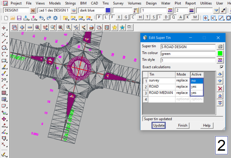
- No – if No then the tin is not included in the Supertin. The tins can be turned on and off without having to remove them from the Tin list.
The example below shows that the ‘survey’ tin is active and included in the Supertin in the first image, then it has been made inactive in the second image, and it has disappeared from the Supertin.
Note: Remember to hit the button to update the Supertin.
If you would like to learn more about the Retriangulate Supertin Panel and how to utilise it,
Tagged: TriangulationTINSSupertinCombined TinsCreateTIN
Related Articles
Quick Triangulation
Retriangulate Function
Triangulate Data
Contents
- 12d Model
- What is 12d Model Software?
- V15 Project Migrate
- Design Quick
- V15 Sharing
- V15 Project Launcher
- Themes
- Object Tree
- Upgrade to 12d Model 15
- Installing and Upgrading 12d Model
- Authorise 12d Model
- Certify Codemeter Dongles
- Enabling Auto Dongle Certify
- Error starting 12d Model
- Silent Installs
- Network Dongles
- Installing and Configuring Codemeter Network Dongle
- Details
- Details
- Project Description
- Managers
- Model Manager Project Menu
- Synchronize Models
- Synchronize Tins
- GIS
- GIS Tools Overview
- REST Feature Service
- Read REST Features Data
- DWG/DXF/DXB
- Importing DEM ascii Files
- Google Earth
- Write Google Earth
- Section plot as attributes
- Old Write KML file
- AutoCAD Drawing Template
- AutoCAD Export Map File
- Write DWG – Export 12d Model Attributes
- Convert .lmf to .label_mapfile
- Create / Edit Mapfiles
- Applying Mapfiles
- Converting .mf to .mapfile
- Create/Edit .mf
- Populating Range File Panels
- Slope Range File (1v in)
- Slope Range File (Degrees)
- Height Range File
- Aspect Range File
- Area Range File
- Depth Range File
- Slope Range File (Percentage)
- Convert Text Strings to 3d Strings
- View Toolbar
- Plan View Properties
- Clone/Copy a View
- Changing a Views Background Colour
- Model Order – Plan View List
- Utilities
- Remove
- Remove Model from a View
- Remove All Models from Project
- Remove Models from Project
- Add Model to a View
- Add All Models to Project
- Add Model to Project
- Save All Models
- Save a Model
- Share Project Models
- Add Shared Models
- Remove Shared Models from Project
- Synchronize Shared Models
- Delete All Models
- Delete Empty Unlocked Models
- Delete a Model
- Create
- Curve/Spirals
- Protected: Temporary Post
- Tools
- Cut / Fill
- Cut & Fill Tadpoles by definitions
- Edit Raster Element
- Create Raster Element
- Importing Nearmap Images Into 12d
- String Inquire or Super String Inquire
- Export
- IFC
- IFC File Export – Distorted or No data displayed in Navisworks 2021
- IFC Writer Global ID and GUID
- 12d Model data into Revit (using IFC Files)
- IFC File Export – Distorted / Jagged Objects in Navisworks 2020
- Create
- Trimesh BIM Objects Create Trench from WNE
- Road Signs
- Trimesh BIM Objects Apply
- Trimesh BIM Objects Create
- Trimesh BIM Objects Create from 12da
- Trimesh BIM Objects Create from Path
- Service Chamber Many
- Service Chamber
- Split Trimesh by Vertical Plane
- Import
- Check Polygon BIM Menu
- Check Breaklines BIM Menu
- Timelines
- Visualisation Quick Timeline
- Chainage Timeline
- CAD Control Bar
- CAD Control Bar – How to utilise it
- Dimension Style – Arrows edit for small distance
- Utilities
- Dimension Style – Arrows edit for small distance
- Super Alignment Reference Table
- Cad Table and CSV files
- CAD Point Toolbar – Medial Axis Centre
- CAD Point Toolbar – String IPs
- CAD Point – Relative
- CAD Point Toolbar – Divide String by Chainage Length
- CAD Point Toolbar – Divide String by Number
- CAD Point Toolbar – Divide Segment by Chainage Length
- CAD Point Toolbar – Divide Segment by Number
- CAD Point Toolbar – Radiation
- CAD Point Toolbar – Between Points 3d
- CAD Point Toolbar – Between Points
- CAD Point Toolbar – Projection
- CAD Point Toolbar – Deflection
- CAD Point Toolbar – Chainage Offset Extended
- CAD Point Toolbar – Drop Perpendicular
- CAD Point Toolbar – Angle
- CAD Point Toolbar – Chainage Offset
- CAD Point Toolbar – Offset
- CAD Point Toolbar – Bearing and Distance
- CAD Point Toolbar – Chainage
- CAD Point Toolbar – Mid-Point
- CAD Point Toolbar – IP
- CAD Point Toolbar – Centre
- CAD Point Toolbar – Mid-segment
- CAD Point Toolbar – Point
- CAD Intersection – 2 Points and 2 Distances
- CAD Intersection – 2 Points and 2 Bearings
- CAD Intersection – 2 Points with Bearing and Distance
- CAD Intersection – 2 Segments
- CAD Intersection – 2 Offset Segments
- CAD Line – Tape Baseline Absolute
- CAD Line – Tape Baseline
- CAD Line – Traverse Edit
- CAD Line – Traverse Append
- CAD Line – Traverse
- CAD Line – Perpendicular
- CAD Line – Tangent
- CAD Line – 2 Points
- CAD Circle Toolbar – 3 Points
- CAD Circle – Centre and Circumference
- CAD Circle – Centre and Point
- CAD Circle – Centre and Radius
- CAD Circle – Point, Radius and Bearing
- CAD Circle – 2 Points and Radius
- CAD Circle – 2 Points
- CAD Circle – 2 Directed Tangents and Radius
- CAD Circle – 2 Tangents and Radius
- CAD Circle – 3 Directed Tangents
- CAD Arc Toolbar – Fillet by Start Point
- CAD Arc Toolbar – Fillet
- CAD Arc Toolbar – Start Point Radius Chord Length and Bearing
- CAD Arc Toolbar – Centre Start Point and Sweep Angle
- CAD Arc Toolbar – 3 Tangents
- CAD Arc Toolbar – Centre, Radius and End Points
- CAD Arc Toolbar – Centre and End Points
- CAD Arc Toolbar – Start Point Radius and Bearing
- CAD Arc Toolbar – Start Point Radius and Chord
- CAD Arc Toolbar – 3 Directed Tangents
- CAD Arc Toolbar – 2 Points and End Bearing
- CAD Arc Toolbar – 2 Points and Arc Length
- CAD Arc Toolbar – 2 Points and Radius
- CAD Arc Toolbar – 2 Directed Tangents and Radius
- CAD Arc Toolbar – 2 Tangents and Radius
- CAD Arc Toolbar – 3 Points
- CAD Polygon – Boundary Polygon
- CAD Polygon – Polygon Free Hand
- CAD Polygon – Polygon Inscribed
- CAD Polygon – Rectangle From 3 Points
- Rectangle from Width and Height
- CAD Polygon – Rectangle from 2 points
- CAD Text – Special Character Map
- CAD Text – Label Perpendicular Offset
- CAD Text – Delete
- CAD Text – Create
- CAD Text – Edit
- CAD Symbol – Create
- CAD Symbol – Edit
- CAD Hole – Remove
- CAD Hole – Add
- CAD Fill – Solid Many
- CAD Fill – Solid
- CAD Image – Delete
- CAD Image – Insert
- CAD Image – Change Height
- CAD Image – Change Width
- CAD Image – Scale
- CAD Image – Rotate
- CAD Image – Move
- CAD Modify – Mirror X Axis
- CAD Modify – Scale Dynamic
- CAD Modify – Scale
- CAD Modify – Mirror Y Axis
- CAD Modify – Mirror
- CAD Modify – Rotate
- CAD Modify – Array
- CAD Modify – Copy
- CAD Modify – Move
- CAD Vertex – Append
- CAD Vertex – Extend by Length 3d
- CAD Vertex – Extend by Length
- CAD Vertex – Extend 3d
- CAD Vertex – Extend
- CAD Vertex – Move 3d
- CAD Vertex – Move
- CAD Segment – Remove 3 Points Curve
- CAD Segment – Insert 3 Points Curve
- CAD Segment – Radius
- CAD Segment – Colour
- CAD String – Trace
- CAD String – Offset
- CAD String – Join Fillet
- CAD String – Join Many
- CAD String – Join
- CAD String – Cross Split
- CAD String – Split
- CAD String – Link Clip
- CAD String – Clip Internal
- CAD String – Clip
- CAD String – Extend by Chainage Length
- CAD String – Extend
- CAD String – Trim
- CAD String – Parallel
- CAD String – Copy
- CAD String – Reverse
- CAD String – Open
- CAD String – Close
- CAD Delete – String
- CAD Delete – Segment
- CAD Delete – Vertex
- Text and Tables
- Check / Clash
- Check Polygon
- Check Breaklines
- Create Supertin
- Quick Triangulation
- Retriangulate Function
- Triangulate Data
- Exporting a 12d Supertin
- Tin Render Settings
- Recalc Supertin
- Edit Supertin
- Add Breaklines to a Tin
- Flip Tin Triangles
- Tin Style
- Tin Edit Function
- Retriangulate without a Panel
- Retriangulate TIN
- Tin Depths Colour
- Slope Analysis Colouring
- Aspect Analysis Colouring
- Tin Height Colour
- Reset Tin Colour
- Replace Triangles Colour by Colour
- Colour Triangles by Strings
- Colour Triangles by Points
- Colour within Polygon
- Colour of Tin
- Contour, Smooth and Label – Label Method
- Colour Contours
- Label Contours
- Contour a Tin
- Change Contours
- Contour, Smooth and Label – Range Tab
- Contour, Smooth and Label – Smooth Contours
- Tin Label Lines for Contours
- Contour, Smooth and Label
- Aspect
- Aspect Analysis 2 New
- Aspect Analysis 2
- Aspect Analysis
- Slope Analysis Flag
- Slope Analysis 2 New
- Slope Analysis 2
- Slope Analysis
- Tins on a Section View
- Tins on a Plan View
- Tins on View Inquire
- Drop Tin to Tin in 3d
- Drop onto Tin in 3d
- Tin Slope Inquire
- Tin Height Inquire
- Depth Between Tins Inquire
- Tin Depth from String
- Depth from Height Inquire
- Tin Colour Inquire
- Tin Aspect Inquire
- Null Triangles by Angle/Length (Seed)
- Null Triangles by Angle/Length
- Null Triangles by Length
- Null Triangles – Outside of a Polygon
- Null Triangles by Centroids
- Tin Include/Exclude
- Null by Strings
- Resetting all Nulled Triangles
- Null by Point
- Null by Polygons
- Add
- Add a Tin to a Model
- Add All Tins to Project
- Add Tin to Project
- Remove Tin from Model
- Remove All Tins from Project
- Remove Tins from Project
- Forced Save All Tins
- Save All Tins
- Save Tin
- Synchronize Shared Tins
- Remove Shared Tins from Project
- Add Shared Tins
- Share Project Tins
- Delete all Tins
- Delete a Tin
- Extras
- Trimble Link – Geoid Error
- Inside 12d Field
- TPS Options (V15)
- Check Coord (V14)
- Check Shot (V14)
- Checks (Setout) (V14)
- Station LSA (V14)
- Station Height Cal (V14)
- Station Helmert (V14)
- Station Standard (V14)
- Station Details (V14)
- Station Setup (V14)
- Show Options (V14)
- TPS Settings
- Target Heights
- Instrument Control Bar
- Instrument Selection – Available Instruments Toggling
- Setup and Configuration
- HotKeys – Panel Sizing
- HotKeys
- Exporting data from 12d Model to Leica
- Exporting a Leica Roads file from 12d Model to Leica
- Exporting a Leica Strings file from 12d Model to Leica
- Exporting a Leica Triangles file from 12d Model to Leica
- Exporting a .DXF from 12d Model to Leica
- Exporting a .CSV file from 12d Model to Leica
- Templates
- Apply MTF Manager (AMM)
- Apply Kerb Return
- MTF Snippet – Driveway Crossing (Layback)
- MTF Snippet – Pram Ramp Crossing
- MTF Analyse Subgrade
- MTF Snippet – Understanding Error Messages
- Components
- Create Roads – Things to Know
- Road Widening
- Drape Alignment String
- X Section function
- Special Chainage File
- Track – Demystifying Track Terminology
- Masonry Block Retaining Wall Creator
- Strings from Sections
- Read X-Section file
- X-Sections from Cuts through Strings
- Create Settlement Model or Rock Strata Model
- Water String
- Convert Water String to
- Water String Conversion to Pts and Lines
- ARR2019 Storm Ensembles
- Downhill Strings
- Create Culvert Headwalls
- Time of Concentration Calculator
- Initial and Continuing Losses
- Pipe Velocity
- Dynamic Drainage – Major and Minor Attribute Groups
- Checking Drainage Analysis Results – Report
- Qx Routing Disabled
- Excess Flow and Qx Routing
- Plot and PPF Editors
- Long Sections
- Measure
- Measure Angle by 3 Points
- Measure Bearing / Distance
- Measure Plan Area
- Measure Surface Area
- Measure Value
- Measure String From Point
- Measure String from Cursor
- Measure Xfall by Strings
- Measure Xfall by Strings (Advanced)
- MetaConnex
- MetaConnex Function Calls
- Chains – Option vs Option Manual
- Chains – Create Edit
- Classify with Attributes
- Create/Edit Attribute Manipulator File
- Attribute Manipulator – U and M Buttons
- Attribute Manipulator – Copy Segment & Vertex Attributes to String Attributes
- Attribute Manipulator – Concatenate Attributes
- Attribute Manipulator – De-concatenate Attributes
- Attribute Manipulator – Calculate Values
- Attribute Manipulator and IFC Property Sets
- Check / Clash
- Check Polygon Utilities Menu
- Check Breaklines Utilities Menu
- Convert to Super Alignment – Elements
- Convert to Super Alignment – IPs
- SPC File
- Edit – Clear All Undos
- Edit – Redo
- Edit – Undo
- Edit – Undo List
- Survey
- Swinging Survey data to Control
- Swinging Survey data to Control by Survey Data Reduction (SDR) Function
- Swinging Survey data to Control by the 2D Helmert (advanced) panel
- Swinging Survey data to Control by the Translate and Rotate tools
- Road Design
- Civil Road Design – Typical Workflow
- Water Network
- List of Stormwater Drainage Attributes
- Create 3d Text
- Attribute Manipulator – Prepare Data for Sharing in a DE Environment
- Attribute Management for Digital Engineering
- 12d Model Projects and Synchronised Environments
- Data Source Box
- Target Source Box
- 12d Model Forum
- Search Bar Toolbar
- Picking with Direction
- Post Under Construction
- User Directory Files
- Plotters.4d / User_Plotters.4d
- Linestyles and Symbols from DWG
- Linestyl.4d
- Colours File
- 12da Library
- Layout.4d
- macros.4d and project_macros.4d
- Project Details (project_details.dtl)
- Workspace Layout (workspace.4dw)
- Setting Text Style favorites
- Loading a Text Style (Font)
- Setups.4d
- Userkeys.4d
- Apply Template and Apply MTF Defaults
- Set up Extra Help for 12d Users
- Sheet Sizes File (Sheets.4d)
- Panel Defaults (DDX files) Dialog Default File
- Creating a Usermenu.4d file
- Toolbars.4d and User_Toolbars.4d
- Names.4d File
- Component Libary File
- Title Block Files (*.tbf)
- Screen Layout Files (*.slx)
- TfNSW Customisation – Links and Information
- Sydney Water Customisation
- 12d Model Software Webinars – All
- Webinar – 12d Design Fundamentals (Introduction to the MTF)
- Webinar – Attributes – What They Are and How to Use Them
Popular Articles
- Tins on a Section View
- Tins on a Plan View
- Plotters.4d / User_Plotters.4d
- Convert .lmf to .label_mapfile
Latest Articles
- Tins on a Section View
- Tins on a Plan View
- Plotters.4d / User_Plotters.4d
- Convert .lmf to .label_mapfile


